Jaguar E-Type S2/Universal Alternator Swap

Every few years, I present a fresh solution for a Series 2 reversed alternator swap. This is the latest and greatest. This alternator was selected because it shouldn't be too hard to adapt to S1 4.2 or S3 applications, as well as S2. This conversion can be accomplished for about a hundred bucks, and requires only light fabrication with simple tools.
 

Mercruiser alternator. PN 805884T or 807653.

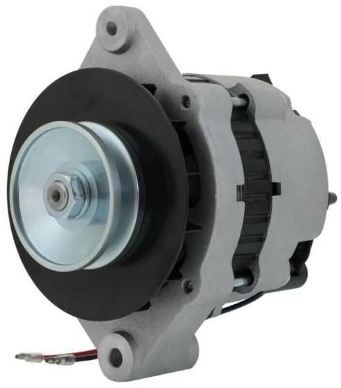
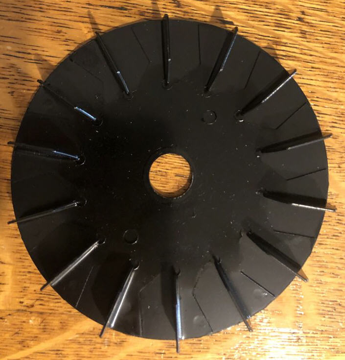
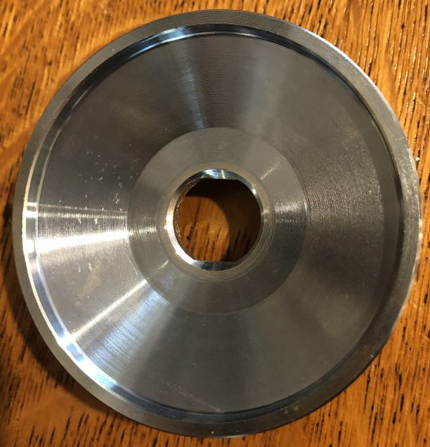
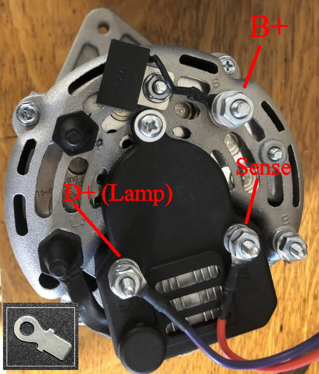
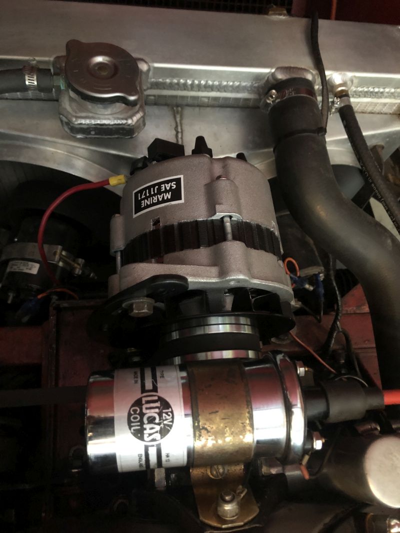
The alternator I selected for this role is commonly used on Mercury Marine stern drives. There are a couple of similar parts, PN 805884T or 807653 seem most applicable. While these may not be familiar in the automotive world,  they are available from marine dealers, or buy them cheaply on EBay or Amazon. What makes this alternator interesting? First, it's a simple internally regulated alternator, so many components can be eliminated. It has a single foot mounting, like the first generation of 11AC alternators. It comes with a pulley and fan, and the fan is omnidirectional so it will function in either forward and reverse mount applications. It has a 5" frame, and the compact size makes it easier to squeeze into tight spaces. Output is typically 65 amps, which is adequate for all stock E-Type applications, including later A/C equipped models. It's regulated to produce 14.7V, which is ideal for AGM batteries. Final bonus, this alternator is SAE J1171 compliant, which means it's safe for sealed engine compartments.

A tour of the alternator:
 

Be sure to order an alternator with a V-belt pulley. (Some come with pulleys for ribbed belts.) Fan is omnidirectional. The alternator can be mounted in forward or reverse applications.
Pulley mates to 17mm shaft with two flats, which is somewhat odd. The pulley is rather thick, which can make clearance tight on S2 applications. The money shot. This is the rear of the alternator, connections are similar to GM internally regulated alternators. Your battery wire connects to the B+ terminal. I'll describe various ways to wire the D+ and Sense connections. Short leads are provided for these connections, but substituting ring terminals (inset photo) makes for a neater installation. 

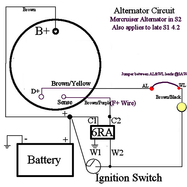
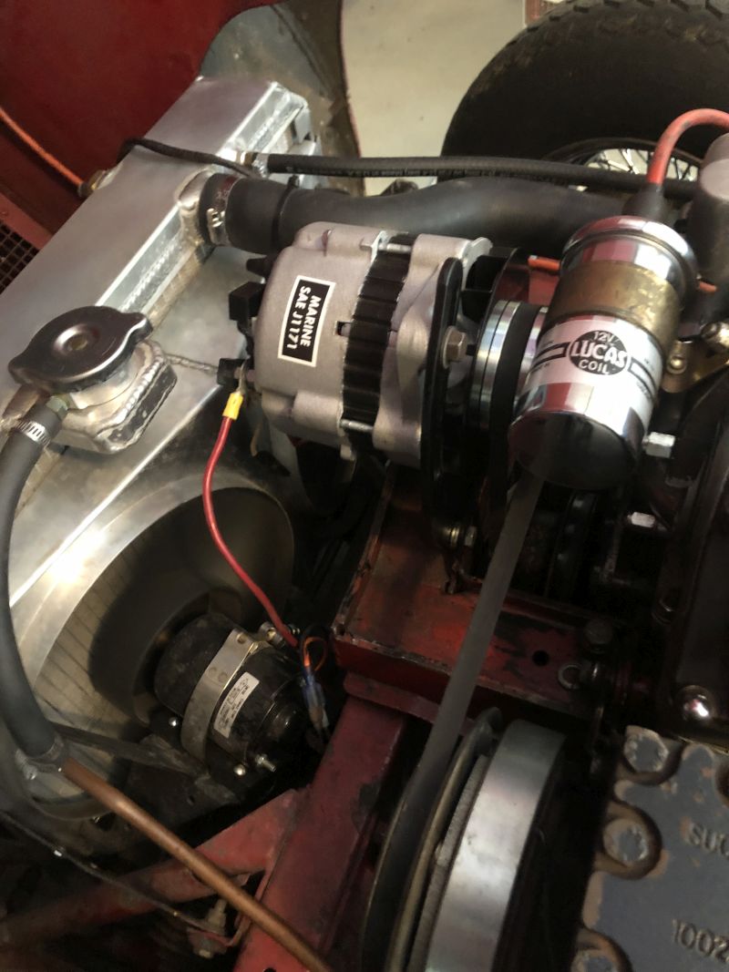
Installation on a Series 2

I installed this alternator on my S2 mule using a very simple wiring plan. Since it's self regulating, the 3AW and 4TR can be eliminated. The internal regulator is bootstrapped by current flowing through the indicator light. Once the alternator begins charging, the light goes out. Wiring is very straightforward.


Original Alternator Circuit, S2 Modifications for Mercruiser alternator. The 4TR and 3AW can be left in place for show, but can be unplugged. The F- wire can be left in place and should be taped off. F+ is connected to the Sense post on the new alternator. The AL and WL wires are bridged with a jumper at the 3AW's location and tucked out of sight behind the voltage regulator. The AL wire then goes to the D+ (Exc) post. 

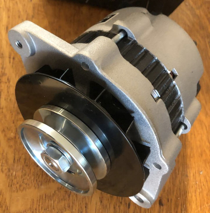
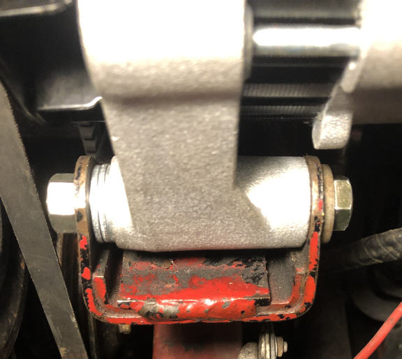
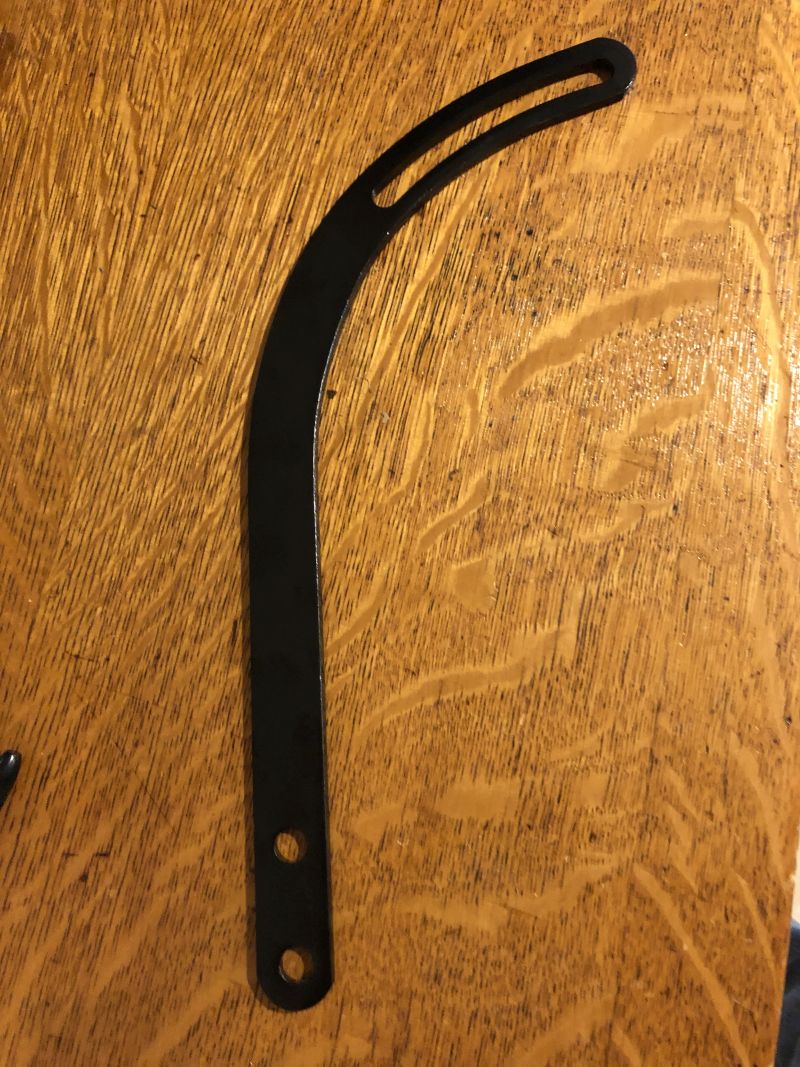
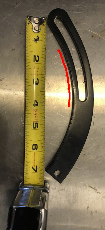
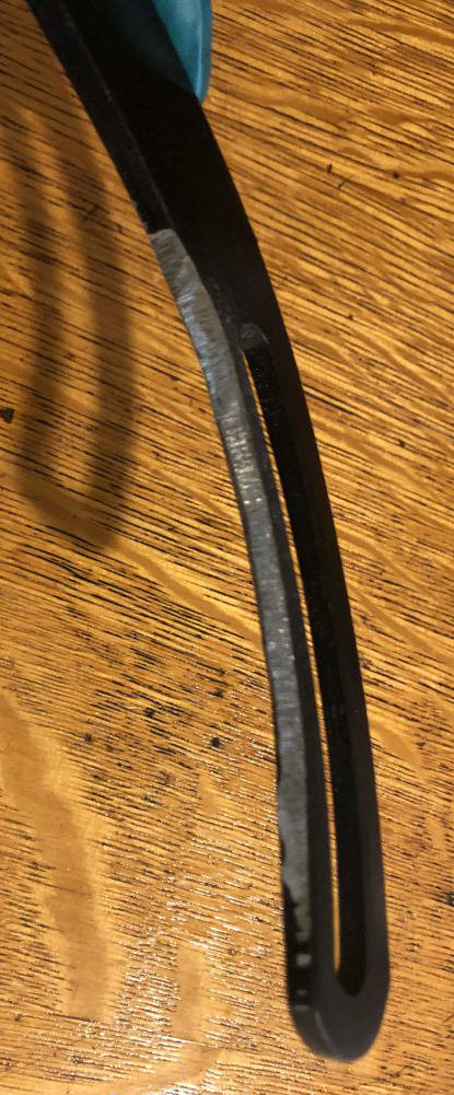
The physical installation of the alternator is straightforward, although some light fabrication is needed to make an adjustment arm. These mods apply to an early Series 2, with the L shaped reverse mount bracket. Later models will require specific tweaks not covered by this faq. The single foot will drop right into the support bracket, with about 1/4" free motion front/back. The alternator should be located forward to allow pulley clearance, but this may vary from car to car. Use washers as needed for spacing, A tensioning arm was fabricated from a Chevrolet bracket. That's really all there is to it.  Some photos:


A few washers are all that's needed to position the alternator in a good fore/aft location. Since the pulley is very thick, the alternator has to be mounted towards the front of the bracket.  The stock tensioning arm will be too short, so a new one has to be cut down from a Chevrolet arm. This arm is widely available on E-Bay, Summit Racing or Amazon in either chrome plate or black finish. Black is more appropriate to the car, and it will be easier to refinish cut edges
The arm has to be cut down so that the distance between the hole and the end of the slot is 7". If you make it longer, you risk denting the bonnet. I found that the area marked in red also had to be ground down just a bit to give good clearance with the alternator fan. 

Although the Mercruiser tension ear is at 12 0'clock (the Lucas is at 10 O'clock), the smaller frame allows it to fit under the bonnet with about an inch of clearance.  It may take a couple of trial fits to get this right. 

Edgewise view of arm after grinding. Remove just a little material at a time. When installing, use washers as necessary to align arm with ear. 
Adjustment arm is only about an inch higher than the alternator. This still allows adequate clearance between alternator and bonnet. There's plenty of room because of the small frame. Fore/aft clearance is a bit tight, only about 1/4" for the pulley. Make sure you space out the alternator with some washers on the foot.

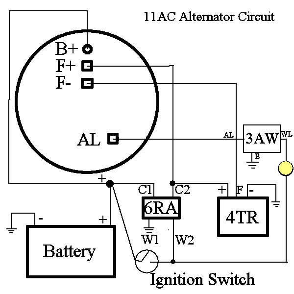
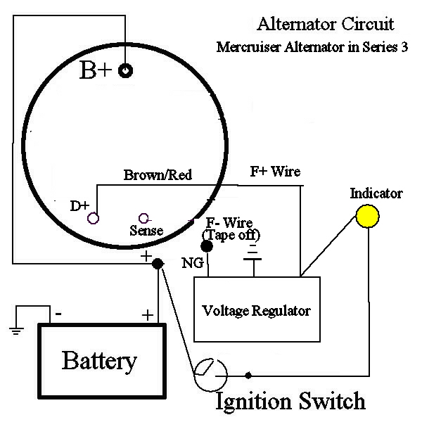
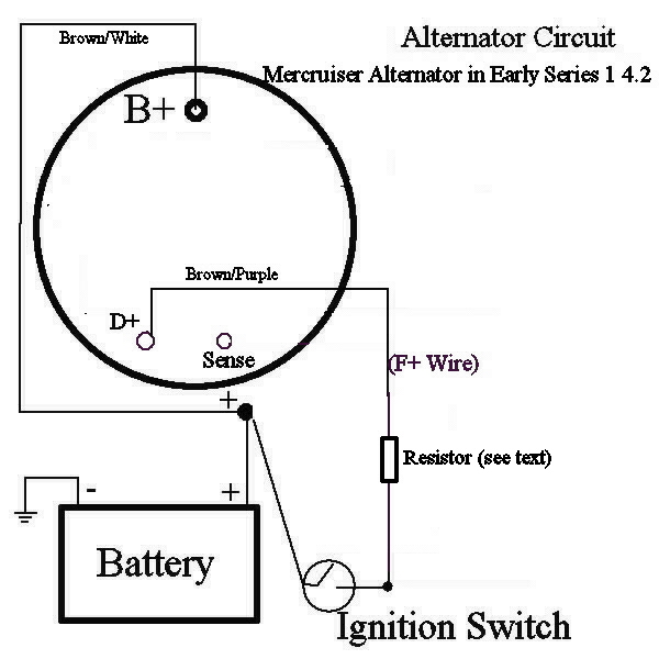
Installation on other models

I'll document other installations as they come up, but for now, here are the wiring diagrams for each E-Type generation. Note that for all models except those with 3AW, all the wiring connections are made at the alternator, no new wiring needed. The conversion time for any car should be no more than two hours.
 

Series 3. There is no available Sense feed for the S3. Don't worry, it's not strictly necessary. Use the Brown/Red (F+ wire) for D+. Tape off the Brown/Green (F- wire.) Although it's not actually in-circuit, the voltage regulator needs to remain in place as the junction for the indicator lamp and D+. And of course, you will need to cobble up a bracket.
 Series 1 4.2 (early). Early cars used an oil pressure switch, rather than a 3AW, and no alternator relay. This makes the wiring even simpler, as the indicator light will not be involved in the charging circuit. Just tape off the F- wire (brown/green.) The stock bracket should work, only a new tension arm would be required.

Note on resistor: If the B+ cable becomes disconnected, or if a positive diode fails, it would be possible for charge current to be backfed through the ignition switch. To prevent damage to the switch, alternator and wiring harness, a 100 ohm resistor should be installed in-line on the brown/purple wire. This will limit backfeed current.

Series 1 4.2 (late) and all Series 2. The later Series 1's as well as all S2's used a 3AW to operate the indicator light. Jumper the WL and AL leads at the 3AW location, and use the AL wire for D+. Tape off the F- wire, and use F+ as sense. Each model requires a different tension arm. Late Series 2's will likely need a different tension arm from early Series 2's.

Copyright © 2022 CoolCat Express Corp. All Rights Reserved.